MultiSurf - design and build for results
This is New in MultiSurf – from version 5 until version 8.2
New User Interface
Completely revised, clear arrangement, precise information at a glance, direct and fast use, much less mouse clicks and movements:
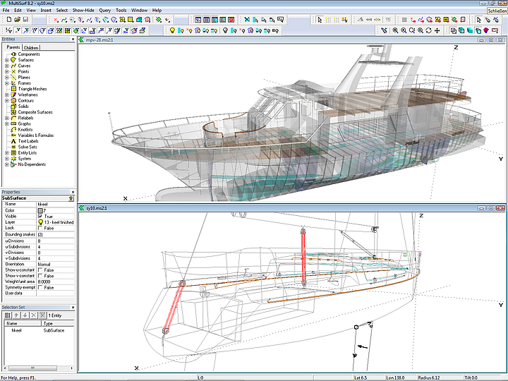
• Shaded View: similar to Wireframe View, but surfaces are displayed transparent; objects can be edited.
• Entities Manager: presents dependency structure (Parents/Children), allows showing, hiding, renaming
• Properties Manager: all properties at a glance; direct changes with few mouse clicks.
• Selection Set Manager, Available Entities Manager: in addition to the known features now with Sort function by Name, Type, Class, Layer, Visibility. Example: suppose, a series of objects has names like winch_p1, winch_p2 ... then all can be selected in a single action via Sort by Name.
Manager windows: freely movable, support of dual screen system.
Toolbar: new toolbar buttons for many functions that were previously accessible only via menus, such as Show/Hide Unselected, Show/Hide Contours, Display Curvature Profiles, Select by Name, etc. Toolbars can be docked or moved to any position.
Mouse function:
• right button: opens context menu (Pan, Zoom to fit, Zoom to area, Zoom in/out, Delete, Show/Hide,Parent/Child, Host/Guest). Also Export DXF in Shiplines View, Export OFE in Offsets View, Mass Properties, Hydrostatics.
• turn wheel: Zoom in/out (to mouse pointer position); direction of zoom selectable.
• press wheel: Rotate model.
New Terminology
Objects --> Entities
Supports --> Parents (Eltern)
Dependents --> Children
Entity rollups – where did AbsPoint and RelPoint go?
Related objects have been effectively combined - the entries in the Properties Manager determine the specific functionality.
AbsPoint and RelPoint --> Point
AbsBead and RelBead --> Bead
AbsMagnet and RelMagnet --> Magnet
AbsRing and RelRing --> Ring
SubCurve and BSubCurve --> SubCurve
PolyCurve and PolyCurve2 --> PolyCurve
PolySnake and PolySnake2 --> PolySnake
SubSnake and BSubSnake --> SubSnake
ProjSnake and ProjSnake2 --> ProjSnake
XContours, YContours, ZContours --> Contours
XPlane, YPlane, ZPlane --> OffsetPlane
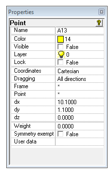
Point - new parents, new functionality
Frame – coordinate system (* = global system)
Point – point of reference (* = frame origin)
dx, dy, dz – distances from the reference point
Dragging – moving constraint of the point; for example, only in X or YZ direction.
Via Multiple Edit it is now possible:
• make in a single action a series of points depend on a new reference point. For example convenient for master curve control points or objects to be grouped for components.
• transfer in a single action a series of points from one coordinate system to another one. For example, in order to make parts of the model geometry rotatable and movable.
• set in a single action the dragging constraints of a series of points. For example: make control points of master curves only movable in YZ direction, so you can drag them around in perspective without changing their X positions.
Multiple Edit
Enhanced concurrent editing of all common properties of the selected objects: color, visibility, dragging, layer, symmetry, reference point, reference coordinate system, etc.
Exempt from symmetry
Objects can be excluded from model symmetry (convenient for rig, sails, superstructure etc.)
Longer Object Names – now up to 32 characters
Quick Point Mode, Quick Spline Mode
Mouse click sets point, bead, ring or magnet; also direct generation of B-spline or C-spline curves via mouse clicks.
Frames
Now selectable: display size, direction of the XYZ axis, left or right handed system.
TrimSurf – new functionality
Automatic use of the edges of the base surface as bounding snakes. For example: if a snake cuts the base surface from edge to edge, just this one is sufficient for support; selection of the desired surface patch by magnet.
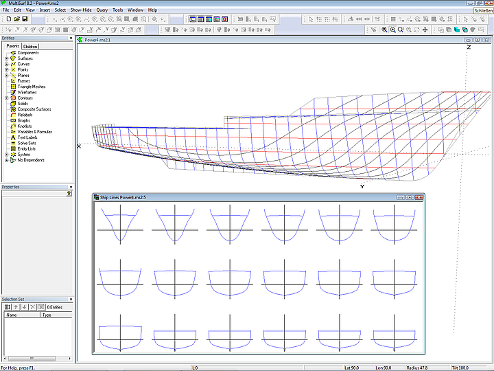
Ship Lines - new options
Reversal of X-direction (now the bow can show to right or left); arrangement of lifts of stations (waterlines, buttocks) in rows and columns, with one side or both sides. DXF output as polycurves or splines.
Text Label
Object to display text; can also show the value of variables and formulas.
Components
Numerous changes in the functionality of components:
• now components form a separate group in the model - improved overview, systematic model structure
• separate display of components and their objects in Entities Manager
• change the display order of the components
• each component has its own name - improved control
• automaticy resolving of name conflicts on loading
• dissolving of a component (Make Internal)
• Current – all objects are added to the current component (similar to Current Layer)
• Component Show, Hide, Delete, Select (for example, assign all parts of a component to a certain layer)
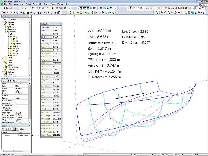
Hydro Balance Component
This new component can be loaded into any model. It directly provides all hydrostatic properties while modeling (no Offset View must be active, no stations hide the essential objects). In combination with the Solve function gravitational and bouyancy forces are balanced in realtime, that is, for a given weight and center of gravity of a design displacement, flotation (sink, trim, heel) and hydrostatics are calculated.
Formulas, Variables
Instead of numerical values variables and formulas can be used. An extensive set of functions is available, among others trigonometric functions, B-spline basis function, area and centroid of surface, XYZ-coordinate values of point, distance between 2 Points, curve length, hydrostatic values, etc.
Some applications of formulas and variables: Determine the main dimension of a hull. Calculate with the Hydro function displacement and center of bouyancy, even while still shaping the hull (without an active Offset View window in the foreground). Or declare height and thickness of a longitudinal section or a tube diameter as variables and change them using the Real Values dialog. Or create a sailplan, that calculates areas and total sail area as well as centroids. Or find the points, that divide a curve automatically into equal portions, for example for the construction of the path of longitudinal stiffeners. Or show area of rudder, keel and hull lateral plan and calculate total centre of areas. Or calculate data for a measurement formula.
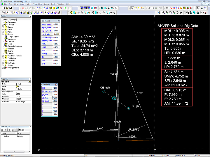
Real Values Dialog
Dialog box for direct input of values of variables as well as display of values of variables and formulas. For example: show the results of the Hydro Balance Component.
Rolling Ball Fillet
Fillet between two surfaces by arc or full circle; radius variation by use of a Graph object.
Tangent Boundary Surface
Defined by 4 boundary curves; automatic generation of internal control points for free forming of the interior shape; tangency and curvature continuity conditions can be imposed along edges.
Expanded Surface
Expansion of a surface; includes marks for stations, strain values, etc.
Composit Surface
Combination of more than one surface into a single entity in a way similar to curves combining into a PolyCurve. The Composite Surface supports a continuous triangle mesh for purposes of flattening and triangle mesh exports.
Radius Arc Type 4
Arc with specified radius and initial direction – convenient for example for deck beams with given radius.
Strain Contours
Provides visualization of strain distribution when surfaces or trimeshes are flattened using Expanded Surface and Expanded TriMesh entity types.
Intersection Point
Intersection of 3 surfaces or 3 planes
Intersection Bead – new Option
Intersection of 2 curves
Solve
Solves geometry problems: for example line tangent to a circle or tangent to 2 circles, rounding between 2 curves, contact point of two curves, etc. In combination with the Hydro Balance Component the flotation for given weight and center of gravity of a hull at free trim can be determined; thus, for various loading conditions one can answer the question about the shape of the DWL when the boat heels, or about the height of the transom above water --> more precise information while drawing the hull lines.
Query
Identifies Breaks (discontinuities in curves and surfaces), lists Evaluation time, Parent/Child (parent-child relationship), Host/Guest (for example:which surface a magnet belongs to, or which points lie on which curve), Extents (expansion of the objects in the selection set or the entire model).