MultiSurf - relational 3D surface modeling
This is New in MultiSurf – version 8.2 - 8.8
MultiSurf – now in 64 Bit
To keep pace in the always changing software business we make the move to 64 bit architecture. This move was also needed to make the SolidWorks Integration modul compatible with SolidWorks 64.
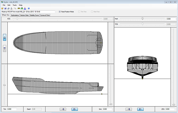
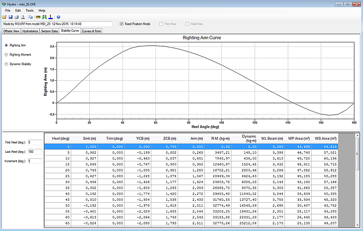
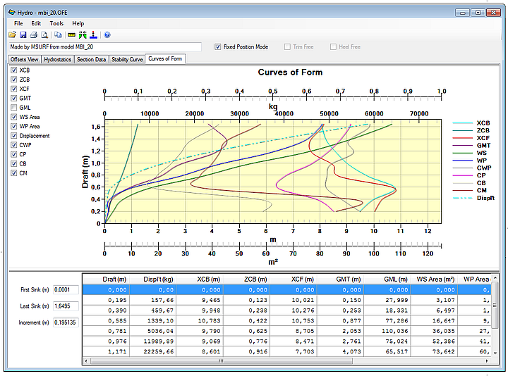
New Hydro Program
The Hydro program has been completely rebuilt. It may not look a great deal different, but much work has been done to enable it in the 64 bit environment. Some enhancements were added like better reports and printing, but the main goal was an up to date program, where enhancements can easily be added in the near future.
*UNIFORM Relabel
All curves and snakes have a relabel attribute, used to distribute the parameter t along the curve (or snake). The default relabel, ‘*’, produces the “natural” labeling for the curve. This natural distribution of the parameter t along a particular kind of curve is described in the Entity Description for that curve (or snake).
In most instances, the default labeling is quite satisfactory. If you choose to relabel a curve, you must create a Relabel entity that specifies the new labeling and include the Relabel entity’s name in the curve’s definition.
Now there is another option. You can choose *UNIFORM, from the set of System Entities, as a relabel parent. The curve or surface will be relabeled with uniform t distribution along the entire arclength. This is a useful tool in controlling the U and V distribution on a surface. If the control curves are relabeled with *UNIFORM the UV lines of a surface will fall in a very predictable pattern. This is useful with lofted surfaces with multiple lofting curves or with curves with very different “natural” t-distribution. Relabeling parent snakes with *UNIFORM in a Blended Surface “fillet” is a good application as well.
Reprise License Manager
MultiSurf has a built in software licensing system to protect you and AeroHydro from unauthorized use of MultiSurf. We have chosen the Reprise License Manager (RLM) as licensing system for its ease of use and the elimination of problems associated with hardware locking. Authorization is only an e-mail or phone call away.
RLM has been updated to version 11.0 for both machine and network license applications. Any older RLM Server which may be enabling other software must be updated to 11.0 with the install of MultiSurf. Older programs can use new servers, but MultiSurf would not be able to use an older version of the RLM server.
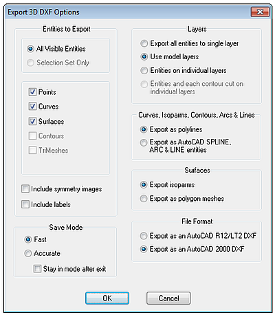
Improved .DXF Export
The image below is an Expanded Surface, with contours, exported from MultiSurf. There is now an option to “Include Labels”, which will export entity names and place them in the .dxf file.
In addition, the edges of the expanded surface have a different polyline definition in your 2D CAD program. This allows them to be easily offset in cases where seam allowances need to be drawn.
New Commands
LoadComponent filename[.ext] name [prefix]
with parent entities selected (order is significant). Default file extension is .MC2. If Prefix is 1, use name as prefix to entity names; if prefix is 0, no prefix is used; default is1.
SequenceDigits [digits]
Sets (or displays) model-level attribute controlling the number of digits to use in program-generated sequences of entity names, like pt001, pt002, pt003...
SetViewLayers [ layer layer ...]
Sets visible layers by view in Wireframe, Shaded and Render views. (If no layers are specified, use model layer settings.)
ExplodeTrimesh [[[[point-color] line-color] point-layer] line-layer]
with one or more trimesh or surface entities selected. Creates a point at each vertex, and a line along each triangle edge of each selected trimesh. (The original trimesh survives intact.)
IF Function bug fix
Any model that uses IF will need to be edited, reversing the order of arg2 and arg3, or the sign of arg1.
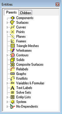
Newer Style User Interface
The interface has been updated to have the look and feel closer to Windows 7 or Windows 8. This is noticeable in the Entity Manager, where the headings are opened by clicking the arrow shapes as opposed to the older style “plus signs”.
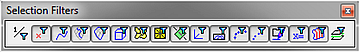
The toolbar buttons have a new look as well. There is a better contrast between a button in an activated and non-activated position.
Context Sensitive Menu Choices for Quick Edits
There are times when Entity Lists and/or a set of parents for contours gets very large and not easily manageable. Many times there is a desire to delete an entity only to find it is a member of an entity list or a contour set and needs to be removed from that list before it can be deleted. To speed up the process of editing these lists of parents, two new context sensitive menu choices were added:
Remove Selected Entities as Parent of Entity List
Remove Selected Entities as Parent of Contours
These new choices can be accessed by right clicking on an entity in the Graphical User Interface, the Entity Manager, or the Selection Set. If the entity is in more than one entity list or contour set, it will be removed from all.
Dongle Support
MultiSurf now supports the use of a dongle enabled licensing system. Plug the dongle into any computer with MultiSurf installed, with the proper license file, and the license will be activated.
IGES Import bug fixes
IGES files which contained surfaces trimmed from a plane generally would no load into MultiSurf. That has been corrected as well as other minor IGES import bugs.
Developable Surface Bug Fixes
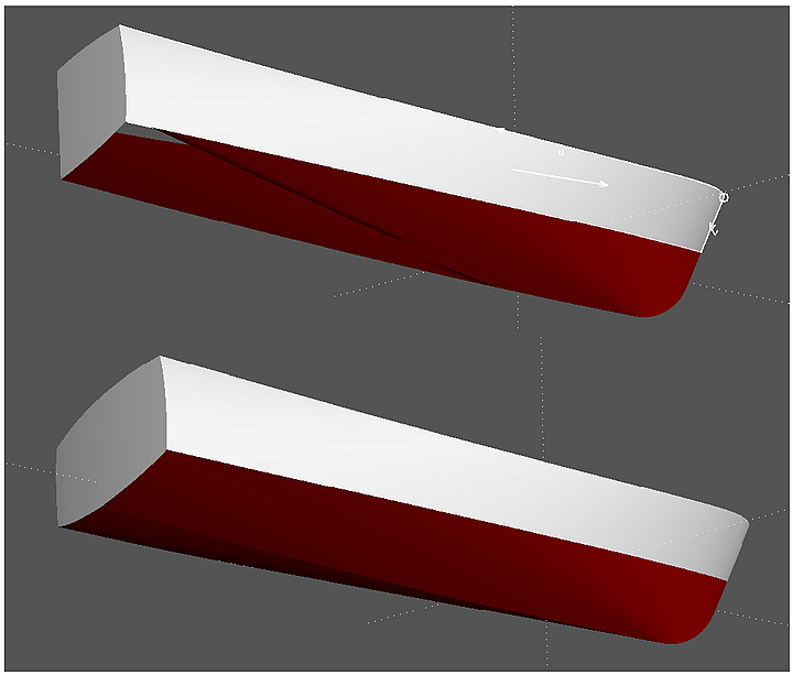
Developable Surface "bottom" – image 2 is from version 8.7.
Real List - new entity
Characteristic data
Unit dimensions = expressed dimensions of the values in the list
Values = entity values to be arrayed
Description
A list of constants, variables, or formulas used as a parent of an entity for the purpose of creating an array. If a bead had a Real List for a parent with values 0.1, 0.15, 0.33, and 0.55, the bead would be arrayed with those values.
Unit dimensions are edited by choosing the appropriate choice from a drop down list.
Values are edited by adding values to the rows, one value per row.
Additional rows are added by right clicking for the choices “Insert Row”, “Append Row”, and “Delete Row”. Reals and/or constants may be used.
Example: ArrayBeadsand Children
Real Sequence - new entity
Characteristic data
Unit dimensions = expressed dimensions of the values in the sequence
Start = first value in the sequence
Increment = distance or value between sequential values
Count = How many in sequence?
Description
A sequence of constants, variables, or formulas used as a parent of an entity for the purpose of creating an array. If a bead had a Real Sequence for a parent it would need a unit dimension of “None”. With a starting value of 0.1, an increment of 0.15, and a count of 4, the bead would be
arrayed with the values of 0.1, 0.25, 0.4, and 0.55.
Unit dimensions are edited by choosing the appropriate choice from a drop down list.
Start: Reals and/or constants may be used.
Increment: Reals and/or constants may be used.
Count: Reals and/or constants may be used.
Example: ArrayBeadsand Children
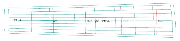
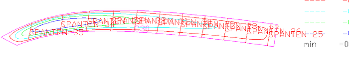
User-settable Text Size in Flattener Output
The first image below is a screen capture of a Flattener output you might see in past versions of MultiSurf. The text size was fine for the surface name and point entities, but when you add stations, it became un-readable.
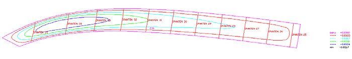
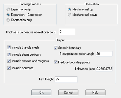
The second image is the default from the updated Flattener, but if that size did not suit, a change could be made and seen in the next export. The third image is the new Flattener options dialog box.
.3DM File Import
File -> Import -> 3DM The option to import files with the .3DM extension is now available.
User-settable Point size in the Model View
The monitors keep getting bigger but the myriad of point entities keep getting smaller. Now you have the option of setting a custom size which fits your comfort and monitor resolution.
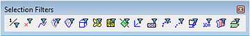
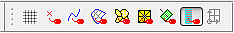
Selection Set Nametags
A new icon (second from the end) gives you the ability to view nametags on the selection set only. This keeps the screen uncluttered by choosing a sub-set of entity names. It is also useful in editing entities with large a large number of parents. Reordering the boundary snakes in the Trimmed Surface was the origination of this enhancement request.
Show/Hide Parents on Entity Manager Right Click Menu
Right-click on an entity in the Entity Manager and you now have the option to show or hide the entity’s Parents.
Surface Orientation View
Beginning with MultiSurf v8.8, the Surface Orientation view provides a simple way to verify and change the orientation of surfaces. This is convenient for example when you check the orientation of panels for hull or deck plating before adding thickness in the plate expansion with Flattener.
To open a surface orientation view, select View/ Display/ Surface Orientation. The following dialog will open:
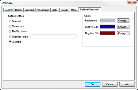
The “Surface Entities” options allow you to select which surfaces will be included in the view. The “Colors” options allow you to select which colors are used to display the positive and negative sides of each surface, as well as which color to use for the view’s background. After clicking the “OK” button, the view will appear and the selected surfaces are displayed with the sides shaded according to their orientation. Surface orientation can be easily changed by clicking on a surface and editing its orientation in the Property Manager.